
Edge AI Boards Under Real Thermal Load: What Actually Survives a Sealed Enclosure
By Hassan Ali, CTO · September 2026
Quick answer: Published TOPS figures are burst numbers measured on an open bench with free airflow. Put the same board in a sealed enclosure and the air around it settles well above outside ambient, the silicon reaches its junction limit, and it clocks itself down. Plan on somewhere between 55% and 75% of the burst figure as your sustained number, size the enclosure before you pick the board, and validate with a soak test at your worst-case ambient rather than a benchmark.
Every edge AI board is sold on a number. Sixty-seven TOPS. Twenty-six TOPS. Thirteen TOPS. Those numbers are real, and they are measured honestly, on a development kit sitting in open air with a fan on it and a room at 22 °C.
Almost nothing ships that way. The board ends up bolted inside a sealed box on a pole in a paddock, or in a switchboard cavity beside a motor drive, or behind an access panel that faces west and takes afternoon sun for four hours. The enclosure is IP66 because water and dust would kill it otherwise, and IP66 means no vents, and no vents means the only way heat leaves is by crossing the enclosure wall.
That single constraint decides more about your delivered performance than the choice between one silicon vendor and another. This is what it looks like when you take it seriously.
Why the desk benchmark misleads you
On a bench, the board is surrounded by effectively infinite room-temperature air that moves freely. Heat leaves the heatsink almost as fast as the silicon makes it. The junction stays comfortably below its limit, the clocks stay high, and the number in the datasheet is achievable more or less indefinitely.
Seal that same board inside a box and you insert two extra thermal resistances between the silicon and the outside world. First the heat has to get from the heatsink into the trapped internal air. Then it has to get from that internal air, through the enclosure wall, into the outside air. Neither step is free, and the second one is usually the bottleneck.
The result is that internal air temperature rises until the heat entering it equals the heat leaving through the walls. Everything inside then runs at that raised baseline. A board rated to throttle at 85 °C junction does not get 85 degrees of headroom from a 25 °C morning. It gets 85 minus whatever the inside of the box has settled at, which on a hot day in direct sun can be 60 or 65 before the electronics contribute anything at all.
The number that actually constrains you
You can estimate this before you buy anything. For natural convection on a sealed metal enclosure, a widely used planning figure is roughly 5 to 8 watts per square metre of external surface, per degree Celsius of rise above outside ambient.
Take a fairly typical roadside or field enclosure at 300 by 200 by 120 mm. Its external surface comes to about 0.25 m², and you should discount the face bolted against a wall or pole because it sheds almost nothing. Allow a 15 °C internal rise, which is already generous if the box sees sun, and you land near 20 to 30 watts of total dissipation.
That figure is the whole budget. Not the compute budget. The budget for the compute module, the power supply losses, the modem, the camera, the sensors, and anything else in the box. A 25 W compute module alone has already spent it.
| Enclosure (external) | Approx. usable area | Budget at 15 °C rise | Realistic compute share |
|---|---|---|---|
| 200 × 150 × 80 mm | ~0.11 m² | ~8 to 13 W | 5 to 8 W |
| 300 × 200 × 120 mm | ~0.25 m² | ~19 to 30 W | 12 to 20 W |
| 400 × 300 × 150 mm | ~0.45 m² | ~34 to 54 W | 22 to 38 W |
| 600 × 400 × 200 mm | ~0.90 m² | ~68 to 108 W | 45 to 75 W |
Treat those as first-pass planning numbers for a vertical, unpainted-to-mid-colour metal box in shade, with no forced air. Direct sun, a dark powder coat, dust films, or a horizontal top surface all push them the wrong way. Solar gain alone can add tens of watts of equivalent load to a box in an open field.
What this does to the boards people actually shortlist
Rather than repeat vendor benchmarks, here is what the published envelopes mean once you put them inside that budget.
| Platform | Published headline | Configurable power | What the enclosure does to it |
|---|---|---|---|
| Jetson Orin Nano Super (8 GB) | Up to 67 TOPS INT8 | 7 W / 15 W / 25 W modes | The 25 W mode is the one the headline number assumes. In a mid-size sealed box that mode alone consumes the entire thermal budget, so most real deployments end up pinned at 15 W, which is a deliberate, supported choice rather than a failure. |
| Raspberry Pi 5 + Hailo-8L M.2 | 13 TOPS on the accelerator | Accelerator is low single-digit watts; the Pi 5 host is the bulk of the load | The accelerator is not your thermal problem. The host is. The Pi 5 starts easing clocks in the low eighties Celsius, and in a sealed box that arrives early, dragging pre- and post-processing down even while the accelerator is still comfortable. |
| Hailo-8 on an industrial carrier | 26 TOPS | Accelerator in the low watts, host chosen by you | Decoupling the accelerator from a fixed host is the main advantage. You can pair it with a low-power host and spend your thermal budget where the work actually is. |
| MCU-class with an NPU | Sub-TOPS | Milliwatts to low watts | Thermally free. If the task is anomaly detection, keyword spotting, or a small classifier, this ends the thermal conversation entirely and it is the most underused option on this list. |
Notice what is not in that table: a winner. The honest answer is that the enclosure and the duty cycle choose the board, not the other way around.
The shape of the curve
Run a sustained workload on a board in a sealed box and the trace has a characteristic shape. Full speed for the first minutes while the thermal mass absorbs energy, then a decay as the internal air heats up, then a plateau once heat in equals heat out.
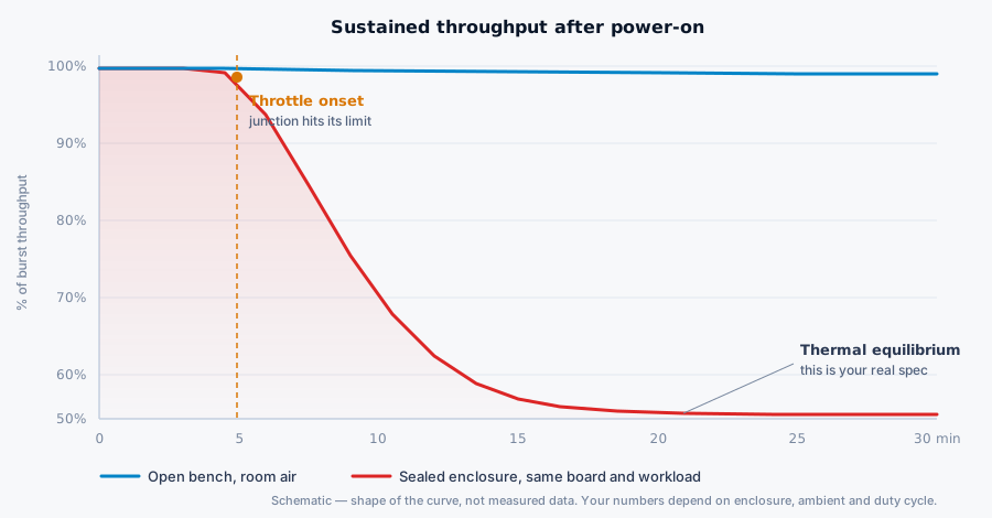
That plateau is the only figure worth designing around. It is also the figure that almost never appears in a comparison article, because reaching it takes forty minutes of boring soak time per configuration and a benchmark that takes forty minutes does not make a good chart.
Where the heat actually gets stuck
When a design misses its thermal target, the fault is rarely the heatsink. It is usually one of these.
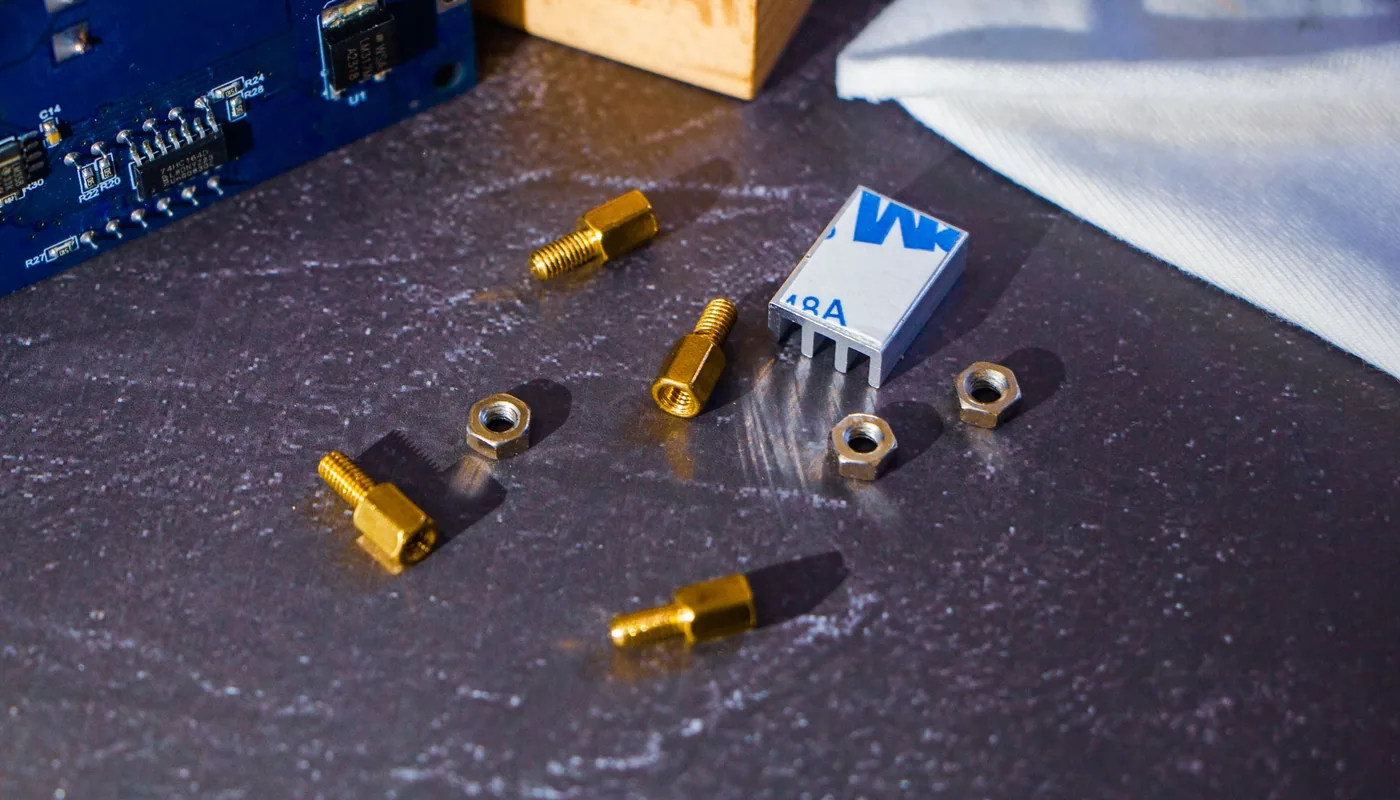
- The interface material. Thermal tape is roughly an order of magnitude worse than a properly applied paste or a graphite pad. On a 15 W module, swapping tape for a decent pad can be worth several degrees at the junction for a few dollars.
- Trapped internal air. A heatsink radiating into still air inside a sealed box heats a small pocket and then stops working well. A cheap internal circulation fan, which does not breach the IP rating because it never touches outside air, moves that heat to the enclosure wall and is often the highest-value change available.
- No path to the wall. The most effective sealed-enclosure designs conduct heat directly from the module to the enclosure body through a metal bracket or a thermal pad against the chassis, turning the entire box into the heatsink.
- Solar gain nobody budgeted. A sunshade with a 20 mm air gap over the top and west face is inexpensive and routinely worth more than any electronic change.
- Orientation. Fins need a vertical path for convection. A heatsink mounted so its channels run horizontally can lose a large part of its rated performance.
How we test it
The test that matters is not a benchmark suite. It is a soak.
- Real workload, real model. Not a synthetic loop. The actual pipeline, at the actual frame rate, with the camera and the encoder and the uplink running, because those consume both power and CPU.
- Real enclosure, real mounting. Sealed, with the production gland plate, mounted the way it will be mounted. A box lying open on a bench is a different thermal system.
- Worst-case ambient. For Australian outdoor deployments that means planning to 45 to 50 °C ambient with solar load, not a 22 °C lab. A chamber is ideal. A closed car in the sun is a surprisingly serviceable substitute early on.
- Soak past equilibrium. Log until the internal air temperature has been flat for at least thirty minutes, then keep going another hour. Record the sustained throughput at that point.
- Then design for the plateau. If the plateau does not meet the requirement, the fix is thermal or architectural. It is not a firmware setting.
This is the same discipline behind the constraint we were working to on an inline weld seam inspection cell, where every weld had to be graded inside a 45 ms line window. A deadline like that is only meaningful if it still holds on the two hundredth unit of a hot afternoon shift, which means it has to be proven at thermal equilibrium rather than in the first minute after power-on.
What we tend to deploy, and why
There is no single answer, but there are consistent patterns.
- When the constraint is latency and the box can be made big enough or actively cooled, a Jetson-class module pinned to a mode we can actually sustain. Choosing 15 W and hitting it every cycle beats choosing 25 W and throttling unpredictably.
- When the constraint is power or the enclosure is small, a discrete accelerator beside a modest host, so the thermal budget is spent on inference rather than on a general-purpose CPU that is idle most of the time.
- When the task is narrower than people assume, an MCU-class part with a small NPU. A great many real problems are anomaly detection or a handful of classes, and solving those on a part that dissipates a fraction of a watt removes the thermal design problem instead of managing it.
- When it genuinely will not fit, we say so early. Sometimes the honest answer is a larger enclosure, a shaded mount, or moving the inference off the device entirely. That conversation is much cheaper in week one than after tooling.
Frequently asked questions
Why does an edge AI board run slower in an enclosure than on a desk?
A sealed enclosure removes the free airflow a desk provides. Heat has to cross the internal air gap and leave through the enclosure wall, so the air immediately around the board settles well above outside ambient. The silicon sees that raised temperature, reaches its junction limit sooner, and clocks itself down to stay there. Nothing has failed. The board is protecting itself, and the sustained throughput at that point is your real specification.
How much heat can a sealed enclosure actually dissipate?
Plan on roughly 5 to 8 watts per square metre of external surface per degree of rise. A 300 by 200 by 120 mm box has around 0.25 m² of usable surface, so a 15 degree rise sheds somewhere near 20 to 30 watts in total, including the power supply and everything else inside. Sun, dust, and wall mounting all reduce it.
Is a Pi 5 with a Hailo accelerator good enough for production?
It can be, when the workload fits the accelerator and the thermal design is honest. The accelerator is efficient; the host is what heats the box. In a sealed outdoor enclosure through an Australian summer, the host reaches its throttle point early, so the design either widens the thermal path or accepts a lower sustained frame rate. Both are legitimate. Discovering it after deployment is not.
Can we fix a thermal problem in firmware?
Only partly. Duty cycling, batching, lower precision, and a smaller model all reduce generated heat and can recover real headroom. What firmware cannot change is the thermal resistance between the silicon and the outside air. If the enclosure cannot shed the power, software only chooses how gracefully the system gives performance back.
Does a fan break an IP66 rating?
An internal circulation fan does not, because it never exchanges air with the outside. It only stirs the air already sealed inside, which breaks up hot pockets and moves heat to the walls. An extraction fan venting to atmosphere is a different matter and does compromise the rating.
Further reading
- Edge AI development services
- NVIDIA Jetson development
- Raspberry Pi and Compute Module development
- Embedded systems development
- RCM compliance for electronic products in Australia
Incendio Solutions is a Melbourne engineering studio building edge AI, embedded systems and industrial automation from schematic to production line - 15 production programs shipped. If you have a board that benchmarks well and disappoints in the field, send us the thermal constraint and we will tell you straight whether it is recoverable.